This article pertains to coolant level sensors on 1989-1995 E34 models. Other years and models may be different and probably are. I would appreciate input from anyone who has broader knowledge on this.
Background
The coolant level sensor seems to be a relatively high failure device. I have seen many emails about other owner’s problems with this device and the sensor on my 1989 525i has now been replaced twice after the factory original. I thought it would be fun and educational to do a analysis of this device and present it to the BMW public. Maybe we can even figure out what to do to make these things last longer. Although not particularly expensive as far as BMW parts go ($27.50 – Jan 2000), why waste money?
Sensor Operation
The coolant level sensor is an electrical sensor utilizing a movable float and a reed switch to sense when the radiator has a low coolant level and alert the driver to this condition. The float contains a ring magnet which closes the reed switch inside the body of the sensor when there is sufficient coolant in the system. When the coolant drops, the float follows the level, the reed switch is removed from the field of the magnet and the contacts of the reed switch open. The car’s check control module sees the open circuit to the sensor and posts a “Coolant Level” alert to the driver.
Sensor Design and Construction
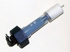
The sensor is a cylindrical plastic device that fits up into an opening in the bottom of the radiator. It is held there with a large plastic nut and sealed with a rubber o-ring. At the top of the sensor is a float that appears to be encapsulated styrofoam with a ring magnet attached at the bottom. The float can slide up and down the upper body of the sensor and is retained at the top by a pair of plastic clips. At the bottom of the sensor is the electrical connector. The sensor body is a two-piece design with the connector half fitting into the upper body and sealed with a rubber o-ring. The two halves appear to be glued together with an epoxy adhesive. This will prove to be it’s downfall…
Diagnosis
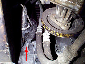
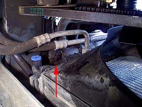
Well, it’s pretty simple, you get a “Coolant Level” alarm on the dashboard display. You stop, open the hood and look at the integrated coolant reserve tank on the radiator and it’s full. Next step is to look down below the bottom radiator hose on the same side as the radiator pressure cap and make sure the sensor is still plugged in. If it’s unplugged, it will give you a false alarm. Here’s two pictures taken from the bottom to give you an idea of where the sensor is located.
You can test the sensor in place with a volt-ohm meter. Unplug the sensor and measure the resistance across the two pins of the sensor. If your coolant level is sufficient, you should measure a dead short across the pins; zero resistance. If it’s open, then the sensor is bad. If it’s not open but showing some resistance, it’s bad. With the sensor unplugged, you should get an alarm from the check control module. If you think your sensor is good, but still get an alarm, short the two pin sockets of the cable together with a short piece of wire. The alarm should go away.
Replacing the Sensor
I found it helpful to put the front end up on jack stands so I could have more room to work. This is a tight area to work in, especially with the A/C hoses in the way.
- Drain the coolant into a bucket. You can see the coolant drain plug in the above picture (it’s blue). Loosen the pressure cap to vent the radiator and allow the coolant to drain.
- Close the radiator drain.
- Unplug the sensor and move the cable out of your way.
- Loosen the plastic nut holding the sensor to the radiator. I found a pair of “Robo-Grips” to work the best. A crow’s foot wrench would probably be the purist’s choice, but I didn’t have one of that size available.
- Pull the sensor out of the radiator and admire.
- Clean the area around the hole where the sensor mounts.
- Install the new sensor. Make sure the new o-ring is clean and in it’s place on the sensor before you place it in the hole. Do not put excessive force on the nut, it just needs to be “firmly” tightened. Let the o-ring do it’s job.
- Plug the sensor cable into the new sensor.
- Pour the coolant back into the radiator.
Analysis of the Old Sensor
The first thing I noticed about the failed sensor was that it seemed to contain liquid. When
shaken, there was a clear sound of liquid inside. After removing the float and the nut, I went
to work on opening it up. The two-piece design was obvious. Upon examination of the seam
between the two halves I noticed that the adhesive holding them together was soft and easily
peeled away from the plastic.
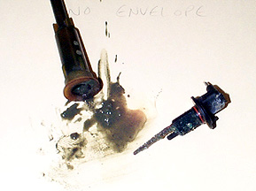
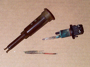
An exacto-knife inserted into the seam quickly plied the two halves apart and a green-brown liquid spilled out along with assorted chunks of material. Examination revealed the remains of the reed switch and wires connecting the switch to the connector. All metal parts were heavily corroded. The wires were completed corroded and no longer attached to the posts of the connector.
Upon close examination of the area where the two body halves meet, I could see “tracks” where the coolant had penetrated the seal and invaded the space inside the sensor. There are probably several factors contributing to the failure of this device:
- The adhesive between the two body halves was attacked by the coolant components. As noted before, the adhesive was soft and easily removed from the seam area.
- The o-ring was ineffective in sealing the device. The o-ring looks to be in good condition with no defects, but clearly failed in it’s duty.
- Hot/Cold cycling. I believe this is the main cause of the failure. As the coolant temperature rises, the air pocket in the sensor expands. As the coolant temperature drops, the air pocket contracts. Over many, many cycles, the seal begins to fail. Then, during hot cycles, air is pushed out. When it cools, the inside contains a vacuum and a small amount of coolant is forced in. After awhile, the sensor is filled, corrosion starts, and the sensor fails.
Possible Fixes
BMW may have redesigned this part for later models. Maybe someone can let me know. Anyway, I
think there are three improvements that could be made. First, the best solution would be
to redesign the body of the sensor so that the seal or “seam” between the two halves is outside
the radiator. This eliminates the possibility of sucking in coolant. The next best fix would
be to fill the cavity of the sensor with a non-reactive, dielectric compound before sealing. This
would eliminate the air pocket and protect against leakage. It would have the added benefit of
not having to redesign and retool for a new plastic body. The third fix is to thermally weld
the two halves together. This would provide a better, longer lasting seal.
What can we try at home? I put the new sensor in before analyzing the old one, so I haven’t tried anything yet. Thermally welding the halves might be a little tricky and unreliable at home, but I’d be willing to take a new one apart and fill it with a dielectric compound. This shouldn’t be too hard to do and should work pretty well.
Wrap-up
This has been fun and I hope I have helped someone else with this problem. If I come across
another interesting failure, I’ll write it up too. Don’t hesitate to email with questions or
comments. If you’ve had a sensor fail in a different manner, please let me know. Thanks.